Figure 1
I think most wings are over-built. This doesn't mean that they can't be broken, just that they are built too strong where they don't need to be, and not strong enough where they could be. Rather than guess, a modeler needs to know how strong the wing needs to be, and where that strength is needed. The simple answer is they can be weak at the tip, and strong at the root. The more complete answer is how much stronger.
It should be obvious that a little upward force near the wingtip creates a much larger force near the root if the fuselage is held still. This force is called a bending moment. It is actually trying to pull the bottom spar cap, putting it in tension, and is compressing the upper spar cap. Both of these forces are greatest near the top and bottom, and decrease to zero near the middle of the spar.
The bending moment at any point is calculated by multiplying a force by the distance between that point and the force. Figure-1 shows these forces on a wing where the tip is on the left, and the root on the right. The 3 ounce force at the tip is shown with the upward arrow. The moment arm is 40". The bending-moment is shown with the clockwise arc on the right, and is 120 oz-in..

The same force produces a bending-moment all along the wing. Figure-2 shows the bending-moment due to the same 3 oz. force at a point closer to the tip. In this case, it produces a bending-moment of only 90 oz-in, 30" from the tip. Any force on the wing contributes to the bending-moment at all locations from the point of the force toward the root. Similarly, the bending moment at any point on the wing is due to all the forces outward of that location on the wing.

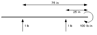
While a wing is generating lift, there is not a single force near the tip, but an upward force distributed all along the wing. The bending-moment at the root is due to the entire force on the halfspan. If the lift is (unrealistically) assumed to be evenly distributed (constant) across a rectangular wing, then the entire force of each halfspan can be approximated by a single force midway between the root and tip. For a plane with a 200" wingspan and weighing 4 pounds, each halfspan is 100" and supports 2 pounds. This results in a bending moment of 100 pound-inches (lb-in) at the root. See figure-3.

Another way to come to the same result is to split each half-span, with each quarter-span supporting one quarter the weight of the plane, 1 lb. The inner quarter supports 1 lb. at its midpoint which is 25" from the root, producing a moment of 25 lb-in. Likewise, the outer quarter supports 1 lb. at its midpoint which is 75" from the root, producing a moment of 75 lb-in. The combined moment for the halfspan is still 100 lb-in.

This example emphasizes how much more the outer portions of the wing contribute to the total bending moment at the root. It also seems to suggest how the moment may be calculated for multiple tapered wings by multiplying the force generated by each section by the distance from the root to where that force is effectively centered. But these examples assumed a uniform lift distribution.
To precisely determine the bending moment, requires an accurate lift distribution for the planform being considered. Even a rectangular planform has a more elliptical than uniform lift distribution. This means that the wing loading across the span varies with span location for all but truly elliptical planforms. Accurate bending moment calculations not only require an accurate lift distribution, but more methodical accounting by dividing the wing into many small sections. This is more easily accomplished today than when Martin Simmons discussed bending moments in a short series of articles entitled Elementary Stress, in the Nov-Dec 1996 issues of RC Soaring Digest. But you might be surprised how little variation there actually is between the too extremes, a rectangular wing with uniform lift distribution, and a triangular planform.
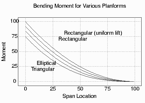
Figure-5 shows the bending moments from root to tip for several representative wing planforms. While we've only discussed the total bending moment at the root, it's important to know the total bending moment at each location on the wing to properly design the spar at that location.

All of the plots are for wings of the same area generating the same amount of lift, but because of their shape, the center of lift may be closer to the root. The rectangular wing has the center of its lift force furthest from the root at midspan, and therefore has the highest bending-moment. The triangular planform has the center of its lift closest to the root, and therefore the smallest bending moment.
The most important thing to see in these plots is that the bending moment decreases very quickly. For the rectangular planform, it is has decreased 25%, roughly 1/8 of the distance from the root to the tip. It is nearly half at approximately 1/3 the distance to the tip. And is approximately a 1/4 at 1/2 the distance to the root. From a different perspective, a wing needs to be twice as strong at the root as it is at 1/3 the distance from root to tip. The outer half need only be half as strong as it is at 1/3 the halfspan. And these ratios are basically the same for all planforms.
The bending moment at the root is four times greater than at midspan.
Making the wing twice as strong at the root than at midspan
is not enough.
It will still break at the root, before it breaks at midspan.
While adding weight in the wings doesn't make the problem any worse,
it does make the plane heavier,
and adding weight to the outer parts of the wings
makes it more difficult to roll the plane,
and less sensitive to thermals.
While bending moments are an important consideration
in designing wing spars,
shear strength is another.
Shear affects wings in the vertical direction,
and is simply the strength needed
to support the load on the wings.
The bending-moment causes horizontal forces
putting the lower spar in tension and
the upper spar in compression.
Shear force affects the entire spar from top to bottom,
unlike the bending-moment
which has maximum affect on the top and bottom of the spar
and zero affect in the middle.
Webbing can significantly increase the shear strength of the spar.
Like the bending-moment,
shear strength is maximum at the root,
where the entire lift generated by the wing supports the plane,
and is zero at the tip.
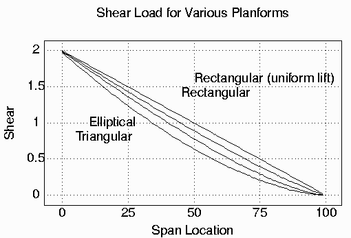
For the example in figure-4, with a rectangular wing having a constant lift distribution, the shear strength at the root is 2 lb. At midspan, it is half, or 1 lb. At 25" from the tip, it is 1/2 lb. It is simply the total lift from the tip to that point on the span. With an accurate lift distribution, the shear strength across the span can be accurately determined using the same methods used to calculate bending-moment. Figure-6 shows the shear strengths for the wing planforms shown in figure-5.

To simplify construction, it seems common to use the same spar design (dimensions and material) for large portions of the wing. This note shows that the bending moment decreases rapidly. If the wing fails, it will most likely fail for a given spar design at the point closest to the root. If a wing does fail away from the root, most likely it will fail where the spar design changes (e.g. no webbing). Since the bending moment reduces quickly, even some moderate strengthening near the root can help tremendously. But it's also important to recognize that material and weight can be removed from the spar further from the root. While this does weaken the spar where it doesn't need to be as strong, it makes the wing lighter and more sensitive to lift.
It is very important to recognize that the numbers used in this note are for illustration only. A 200" sailplane supporting only 4 lbs has both a halfspan and bending moment of 100 which is easy to discuss in terms of percentages. However, it's not weight but maximum load that must be considered, and this typically occurs during a winch launch. The breaking strength of the winch line is often used, and values of 180 to 220 lbs are not unusual.
Knowing the bending moment and shear strength, and how they vary across the span, are important in wing spar design. Spar design is a lengthy discussion and whole books have been written on the subject (Strojnik, Alex, Low Power Laminar Aircraft Structures, 1984). Spar design has also become very sophisticated with the use of various composite materials and structures. And of course, Mark Drela's Allegro is an excellent example. Thanks Ollie for all your help.