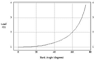
Figure 1 - G-load vs Bank Angle
Uniformly built spars, having the same structure and dimensions from the root to even just halfway to the wing-tip, add weight with little benefit in strength, and this weight is closer to the wing-tips which inhibit rolls in both acrobatic planes, as well as sailplanes. There are some excellent articles and books[2-5], targeted for the hobbyist, but requiring some effort to understand. While spar design may be an interesting engineering challenge, it may be frustrating to the average hobbyist. Uniformly built spars are simple to construct. While qualified experts are developing sophisticated designs for high-performance aircraft, such as the Allegro-Lite[1], little informative seems available for the hobbyist who still builds from materials purchased at local hobby shop or hardware store.
These notes discuss:
Figure-2 shows the maximum load forces at the bottom of a verticle loop. At the top of the loop, gravity is aiding the plane in pulling toward the center of the loop, while at the bottom, it is pulling it out of the loop. The figure shows how the loads increase with speed, and with smaller diameter loops. Even if the plane is not being flown in a complete loop, these numbers still apply if the plane is simply being pulled out of a dive.
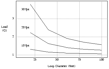
The point is that the maximum load is far greater than simply the weigh of the plane. Three things need to be considered:
The wings are assumed to support themselves, therefore, the wing root only supports the weight of the fuselage and tail. However, this weight may be multiplied many times determined by the maximum-Gs experienced during a flight maneuver. The value of N would be 3, if a 3G flight maneuever is the worst case. This would result in a maximum of N* W b. For a sailplane during launch, it has been suggested that half the breaking strength of the line be used.
The safety-factor accounts for inconsistent construction. These include less than perfect assembly and glueing of the structure, weak spots in materials such as wood, and if composite laminates (fiberglass) were used, inconsistent amounts/thickness/strength of epoxy. A safety-factor value of 2 may be typical.
The maximum wing-load, Lmax, on each half of the wing, is the result of 0.5 * S * N * W b. For an acrobatic plane weight-without-wings of 5 lbs, flying 3G maneuvers, and using a safety-factor of 2, the maximum wing-load would be 30 lbs. For a winch lauched sailplane, considering half the line breaking strength of 80 lbs, and using a safety-factor of 2, the maximum wing-load would be 80 lbs. However, 200lb winch lines are routinely broken by F3b sailplanes. The determination of both the maximum-G and safety-factors values are somewhat of an art. But consider that both results above are considerably greater than the simple weight of the plane.
Consider, for example, the maximum bending-moment of a 200" rectangular wing, and a load of 4 lbs. Assume (incorrectly) that the load is equally distributed over the entire wing. The moment-arm for each half of the wing is simply the distance from the mid-point to the CG of the plane, or 50 in., which is supporting half the load, 2 lbs. This gross estimate results is a bending-moment of 100 in-lbs.
But the wing-load is only equally distributed over an elliptical planform. Any other planform requires some adjustment. Simons[4] suggests that the bending-moment can be estimated by correcting the planform chord dimensions by taking the average of the actual and comparable elliptical chord dimensions. Other factors, such as wash-out or twist, also need to be considered when estimating the lift-distribution across the span. The vortice lattice method is one technique for determining a more accurate estimate of wing loading. See ciurpita.tripod.com/rc/wing
Figure-3 shows how similar the bending-moment curves are for several planforms covering the extremes between the uncorrected rectangular wing used in the estimate, to a triangular (taper-ratio of zero) planforms. A tapered planform with a taper-ratio of ~0.4 is roughly the same as the elliptic curve. These curves show that the maximum bending-moment for a (corrected) rectangular wing is only 93% of the estimate. Likewise, an elliptical wing is roughly 84% of the estimate.
The curves also show how rapidly the bending-moment decreases as the distance from the root increases. They show that the bending-moment is reduced by half at 30% of the span, and to less than 1/4 at mid-span.
Figure 4 - Spar Structure |
     B H3 - b h3
M = -----------
       6 H
|
Figure-5 compares the accurate moment-of-inertia calculation to several approximations. The approximations are based on the cross-sectional area of the spar-cap, A = b Tc. Each approximation multiplies the area, A, by: 1) the full spar-height, H, 2) the distance between the midpoints of both spar caps, (H-h)/2, and 3) the distance between the spar-caps, h = H-2Tc. The curves illustrate how all approximations become increasingly accurate as the spar-caps become thinner.
Only the last approximation, using the distance between the spar-caps, is conservative in that it errors on the side of under estimating the strength. It is also relatively accurate. This approximation has less than 5% error for the case where the spar-caps are less-than 15% of the spar thickness. This is certainly the case for 1/8" spar-caps in a 7/8" spar, more typical in wooden construction. High-performance structures using thin (~3%) carbon-fiber laminates [2] can use the most convenient approximation accurately.
For bending-strength, the spar material is concentrated at the surface of the wings. This is not the case for shear strength. This shear load is resisted by the entire cross section of the spar. Consider, for example, a spar-heigth of 1" with 1/8" balsa web between the spar-caps. Assuming the spar-cap material has at least the shear-strength of balsa, a simplistic approximation for the cross-sectional area is 1" times 1/8" or 0.125 sq.in.
Balsa has a shear-strength of 200psi. The shear web can therefore support a load of 25 lbs. on each wing half. This could support a total wing-load of 50lbs. The shear-web thickness could be doubled such that each wing-half supports 50lbs, or a total wing-log of 100lbs. This would be sufficient for the wing-load of 80 lbs calculated in the earlier example.
The weak spot in a uniformly built spar is nearest the root. If some additional strength is added to the spar structure nearest the root, the spar may also fail near the root, or at the location where the additional support ends. But it should fail under a higher load. In a simple open-bay wing, the spar structure of each bay can be slightly different. While it may not be worth the trouble to optimise the design out to the wing tip, significant improvements can be gained by focusing on a few bays closest to the root, easily doubling the load the wings can support. Figure-1 provides a good reference for how strong the spar in each bay needs to be.
If additional bending-strength is not needed, then a more accurate understanding and analysis can determine where the spar is over-built, indicating where the construction can be simplified, material removed, or smaller sizes used. The benefit is a lighter plane, and improved roll maneuverability for acrobatic planes, and wing-tip sensitivity to thermals in sailplanes.
However, it also seems that strong spars are also used to handle torsional loads. A better understanding of torsional structures and their application would again result in a torsionally stronger wing using less material and having less weight with the same benefits as discussed already.
I wish to thank all those I have corresponded with for their patience in answering my tedious questions, and especially to Marcus Shimazu-Takahashi and his Airbear. Borrowing a line from Marc - I hope this was helpful.