Fig 1
Composite spar materials are changing the way wing spars get their strength because of their high strength to weight and size ratios, and because carbon cloth can can put the strength exactly where it is needed, on the surface of the wing.
The following will first review the loads on a wing, shear and bending moments describing the equations to calculate these values, but also provide enough data for a variety of wing spans to spare most builders the pain of using them. It will then discuss where spars get their strength from skins, tubes and joiner rods.
|
Fig 1 |
|---|
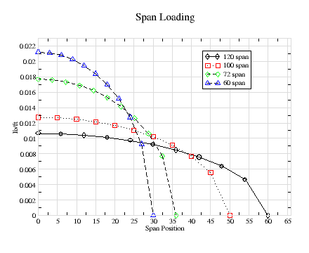
The place to start is with the spanwise loading on the wing. Figure-1 shows the loading for a rectangular planform. Martin Simons explained that except for an elliptical wing planform, the actually wing loading is approximately the average of the actual wing planform and an elliptical planform. There are more acurate ways to calculate this loading using the Votex Lattice Method used in John Hazel's LiftRoll spreadsheet. But given that most planforms are somewhere in between a rectangular and elliptical shape, this particular graph serves as a worst case loading.
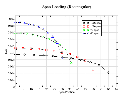
Fig 1a |
|---|
The total load on each half of the wing is half the total load on both wing halves, or 1/2 pound. The loading is calculated per length of span, pound per in, not pound per square inch (psi). Since it is the same for all wings, the maximum loading is highest for the smallest wing, at the root, and is zero at the tip, 30" for the 60" wing. As a check, the loading on the 60" wing should be twice that as the 120" wing.
For these curves, the span is divided into ten span segments, and there are eleven span positions. In order to introduce the notation used in the equations later the follow equation describes a purely rectangular loading (not averaged with the elliptical loading) at each span position
ln = load / span
where load is the total load, one lb, span is the total wingspan, ln is the loading per inch of span at span position n, where n is zero at the root and increments to ten at the tip since there are eleven span positions.
For the 100" wing, this 0.01 lbs/in, 0.0083 lb/in for the 120" wing, and 0.0167 lb/in for the 60" wing.
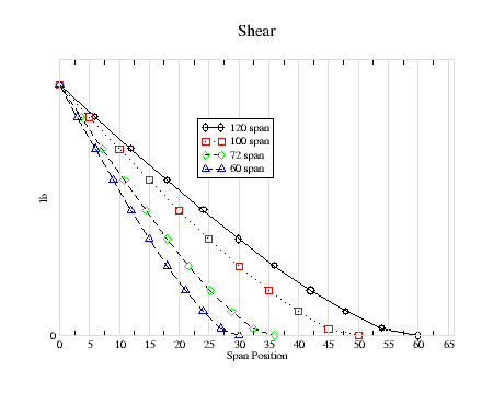
Fig 2 |
|---|
Shear is the verticle load at each span position. It is zero at the tip and the total load on the halfspan at the root. At each span position, it is the total load supported by the wing from that position on the span to the tip. Since all the wings are supporting the same load, 1/2 lbs, that all have the same shear load at the root.
In normal flight, the load on the wings in not the total weight of the aircraft, but only the weight of the fuselage. The wing support their own weight. An aircraft fuselage weight of four lbs results in a shear force of two lbs at the root of each wing. However, the total load supported by the wings may be much larger. The shear force will be five times larger in a 5g turn. For winch launched sailplanes, however, the greatest load is during launch, and it is the total force provide by the winch which may be 200 lbs.
The shear force is calculated for each span segment and added to the shear for the adjacent segment nearer the tip. The shear for a particular segment is determined by calculating the average loading on that segment and multiplying it by the length of the segment. The average loading is calculated by averaging the loading at the span positions at each end of the segment
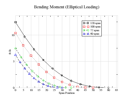
Fig 3 |
|---|
sn = sn+1 + {(dn + dn+1) · (ln + ln+1) / 2}where sn is the shear force, and dn is the distance from the root at span position p.
If the loading were constant (e.g. rectangular), the shear force would constantly increase (be a straight line) from the tip to the root. Since it is somewhat elliptical and smaller near the tip, Figure-2 shows that it increase more sharply as it gets closer to the root. But for all size wings, it is the same value at the root, 1/2 lb.
The bending moment is the force rotating (vertically) the wing around the fuselage. A simple way to calculate it assuming a constant (rectangular) loading is to assume that the entire load on the halfspan is applied in the middle of the halfspan.
For example, consider a 100" wing that must withstand a 200 lb winch load. Each wing support half the load, 100 lbs, and since each half of the wing is 50", the midpoint is 25" from the root. The bending moment is 100 lbs multiplied by 25" or 2500 in-lbs, or 209 ft-lbs. Since we're taking half the load on half the wing, and then halfway from the root and tip, its the total load multiplied by the total wingspan divided by eight (200 lbs · 100" / 8). And this is almost always a worst case (maximum) value.
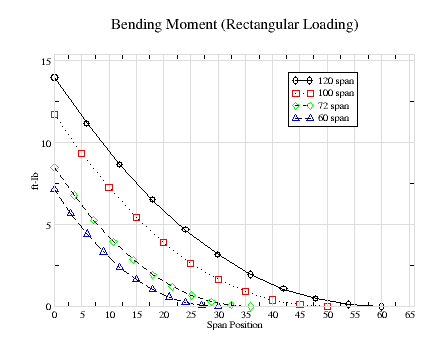
Fig 4 |
|---|
The bending moment at each span position is calculated similarly to the shear force calculation for each span segment, using the average shear force instead of the spanwise loading at the span positions at each end of the segment. Unlike the shear calculation, it is only the calculation for that segment
bn = { (dn + dn+1) · (sn + sn+1) / 2 }where bn is the bending moment at span position p.
Figure-3 and 4 providing bending-moment data for elliptical and rectangular wing loadings. These represent the best and worst cases. They both show how rapidly the bending-moment increase nearer the root. It has dropped by roughly half at only 1/3 the distance to the tip. Using the worst case approximation, the maximum bending moment is 15, 12.5, 9 and 7.5 in-lbs for the 120" through 60" wingspans respectively. We see that the graphs shows values that are all less than these worst case value for the the more realistic rectangular spansize loadings as shown in figure-1.
|
This section simply collects information.
Table-1 provide the standard equations for both tube and rectangular structures. Please note that a tube with an ID of zero represents a solid rod, and similarly, for rectangular spars, values of zero for b and h represent a solid spar. And that b represents the total unoccupied space under the spar cap, as in the case of an I-beam or a hollow rectangular beam. The section modulus multiplied by the material strength results in the bending-moment resistance. |
|
|
| ||||||||||||||||||||||||
|
Tables-2 and -3 are from a Martin Simons' article in the November 1994 issue of RCSD. Table-4 is from a note by Professor Mark Drela in the May 2004 RCSD on carbon rod sizing. The Composite ST website lists the strength of carbon rods as 275000 psi. It is interesting to note the differences in values.
Table-5 is another note from Drela on material strengths values determined mostly by Phil Barnes. in the December 2003 RCSD.
| |||||||||||||||||||||||||||||||||||||||||||||||||||||||||||||||||||||||||||||||||||||||||||||||||||||||||||||||||||||||||||||||||||||||||||||||||||
Another consideration is that while carbon cloth on the skin is exactly where it's strength is most needed, the thin material may not be strong enough to resist the shear forces While the bending moment resistance of the wing is proportional to the cross-sectional area of the carbon material multiplied by the wing thickness, the shear strength is only proportional to cross-sectional area. So, for example, while the carbon tubing may no longer be required for bending-moment resistance, it may be needed for shear strength.
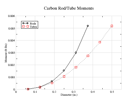
Fig 4 |
|---|
Figure-4 provides these values for solid rods and tubes with a wall thickness of 0.032". These values need to be multiplied by the material strength (see table below). A larger diameter hollow rod can clearly be stronger than a solid rod of smaller diameter and equal weight.
As an example, consider the required carbon rod diameter required for a 100" span wing with a maximum winch load of 200 lb. From Figure-3, the maximum bending-moment is about 11 lb-in, which translates to 2200 in-lb, or 184 ft-lbs. The material strength for a pultruded carbon rod with safety margin is 100,000 psi. Dividing 184 by 100,000 results in a value of 0.00184, which translates to a rod diameter of about 0.275" from figure-4, or a tube diameter of about 0.312".
A 0.275" diameter wing joiner rod requires a tube with the same inside diameter. Assuming a 1/32" tube wall thickness requires an outside diameter of 0.3375". This exceeds the tube diameter (0.312") required to provide the required bending moment resitance of the wing. In other words, the joiner rod and tube provide twice the required bending-moment resistance.
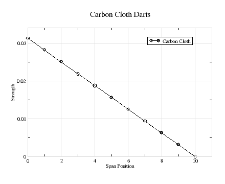
Fig 5 |
|---|
Figure-5 shows a graph for a carbon cloth skin spar that is 1" in width at the root, 1/32" in thickness and a airfoil thickness of 1". These values must be multiplied by the material strength value and can be scaled in thickness, width or heigth. It has a maximum value value of 0.03 at the root. Using the carbon strength value of 100,000, the 1" wide carbon dart provides a bending-resistance of 3,000 in-lbs.
This exceeds what is necessary in the example above where the required bending-moment is only 2200 in-lbs. The carbon could therefore be reduced in width assuming concistent contruction technique. A 3/4" width still exceeds the strength required at the root.
As the chart shows, a triangular shaped dart will reduce its strength proportionately from root to tip. However, Figure-3 shows that the bending-moment decreases rapidly near the root. Therefore, if the trangular dart exceeds the bending-moment at the root, it will exceed it at all span locations.
Considering that the wing joiner rod and the tube already provide twice the required bending-moment resistance, the addition of the carbon dart dart now provides triple the required resistance. Assuming a 12" joiner rod inserted 6" into each wing, Figure-3 shows that the bending-moment has decreased by approximately 20% at the 6" span position for a 100" wing. It has decreased even more for short wings. Therefore, the carbon skin width could be reduced by another 20% to 5/8", and still be excessive at the 6" span position. Furthermore, there is no need for a carbon tube to provide bending-moment resistance.
The shear resistance depends on the cross sectional area of the spar and the material strength. Near the root, this include the wing joiner, carbon skin, the sheeting material (e.g. fiberglass), and the foam. The largest area is occupied by the foam, but the wing joiner provide the most strength. The area of the 0.275" diameter wing joiner multiplied by the material strength, 100,000 psi easily exceeds the shear load at the root of 100 lbs.
5940 = π (0.275 / 2)2 · 100000
Further from the root, past where the joiner rod ends, the carbon skin material provides less strength. Since its strength decrease proprotionally from root to tip, and because the shear load decreases more quickly, if the skin strength is sufficient at the root, it will ne adequate across the span. Assuming a 1" width at the root, the 1/32" thick skin has an area multiplied by th ematerial strength of, which again is sufficient
3125 = 1" · 1/32" · 100000